Product
mightyZAP, the micro linear servo actuating solution
for the era of the 4th industrial revolution
Actuator Lineup Details
17Lf Servo Series Overview
The new mightyZAP servo series with a 17mm diameter motor which improve durability. Provide faster speed under the same rated load specification comparing to the 12Lf series. Overall functionality is almost same as the 12Lf series, but only RS-485 communication and MODBUS RTU protocol are provided, and user expandability has been improved with the expansion I/O port.
Mini Size
Built-in Drive (RS-485)
Data Communication (MODBUS RTU)
Postion Control / Feedback
Current Control / Feedback
Dynamic Speed Control
Expansion I/O Port
Action Feature (User Motion Save & Run – No Coding)
Heavy Duty, Durable 17mm Diameter Coreless DC Motor
17Lf Servo Series Features

- Compact size with built-in drive, position sensor, DC motor and gear box
- Better durability & faster speed under similar rated load comparing to 12Lf series thanks to the bigger 17mm diameter DC motor
- Position, current and speed control along with position & current feedback
- Easy digital I/O control through 4 x Expansion I/O ports (No coding)
- 27/37/50/87mm(*) stroke option
– (*): Each 3mm stroke can be added when adjusting the long stroke limit through Total Manager software. - Rated load of 17N~70N depending on the lead angle for each stroke
– Speed is inversely proportional to the rated load, so the higher the rated load, the slower the speed. - RS-485 MODBUS-RTU protocol applied (IR open protocol is not provided)
- Action feature which enables user’s motion save & run
17Lf Servo Series Digital Archive
17Lf Series Specifications
| Rated Load | Stroke | Communication RS-485 | Rated Load /Max Speed (No Load) | Stall Force at Current (1.6A / 800mA / 200mA) | Mechanical Self Lock (Z Axis Use) | Lead Screw / Gear Ratio / Gear Type |
|---|---|---|---|---|---|---|
| 17N | 37mm (40mm*) | 17Lf-17F-37 | 17N / 105mm/s | 90N / 58N / 23N | No (Pay attention to application) | Lead Angle 20° / 10:1 / Engineering Plastic Gears |
| 50mm (53mm*) | 17Lf-17F-50 | |||||
| 87mm (90mm*) | 17Lf-17F-87 | |||||
| 20N | 27mm (30mm*) | 17Lf-20F-27 | 20N / 117mm/s | Lead Angle 22.2° / 9.3:1 / Engineering Plastic Gears | ||
| 27N | 37mm (40mm*) | 17Lf-27F-37 | 27N / 82mm/s | 96N / 68N / 27N | Lead Angle 15° / 10:1 / Engineering Plastic Gears | |
| 50mm (53mm*) | 17Lf-27F-50 | |||||
| 87mm (90mm*) | 17Lf-27F-87 | |||||
| 35N | 27mm (30mm*) | 17Lf-35F-27 | 35N / 90mm/s | Lead Angle 17° / 9.3:1 / Engineering Plastic Gears | ||
| 50N | 37mm (40mm*) | 17Lf-50F-37 | 50N / 28mm/s | 182N / 129N / 50N | Yes (Applicable) | Lead Angle 5° / 10:1 / Engineering Plastic Gears |
| 50mm (53mm*) | 17Lf-50F-50 | |||||
| 87mm (90mm*) | 17Lf-50F-87 | |||||
| 70N | 27mm (30mm*) | 17Lf-70F-27 | 70N / 30mm/s | Lead Angle 5.82°/ 9.3:1 / Engineering Plastic Gears |
(*): Maximum stroke length when adjusting long stroke limit through Total Manager software
17Lf Servo Series Common Specifications
| Repeatability | Stroke | Unidirectional | |||
|---|---|---|---|---|---|
| 27mm / 37mm | 30μm(0.03mm) | ||||
| 50mm | 40μm(0.04mm) | ||||
| 87mm | 50μm(0.05mm) | ||||
| Mechanical Backlash | 0.03mm(30μm) | ||||
| Rod Type | Metal Alloy Rod | ||||
| Motor Type | Coreless DC (17mm diameter) | ||||
| Rated Voltage | 12V | ||||
| Motor Watt | 3.8W | ||||
| Recommended Duty Cycle | At Rated Load | At Max Applicable Load | |||
| Max 50% | Max 20% | ||||
| Current Accuracy | ±15%at Over 50mA | ||||
| Position Sensor | 10KΩlinear Potentiometer | ||||
| Input Voltage Range | 7 ~13V (Rated 12VDC) | ||||
| Current Consumption | Idle | Rated | Stall | ||
| Default | MAX | ||||
| Under 30mA | 400mA | 800mA | 1600mA | ||
| Audible Noise | Approx. 50db at 1m | ||||
| LED Indication | Two Errors Indications (Input voltage, Overload) | ||||
| Communication Method / Protocol | RS-485 / MODBUS RTU (IR Open protocol is not supported) | ||||
| Expoansion I/O Port | 4 Ports (Function : Switch, JOG, Action Enable, Force Off, PAUSE, STOP, RESTART, Alarm OUT) | ||||
| Ingress Protection | IP-54(Dust & Water Tight) | ||||
| Dimension(LxHxW) / Wight (Dimension excluding the rod-end tip and hinge) | 27mm | 57.5×40.6x23mm / 65.5g | |||
| 37mm | 86.8×57.9x23mm / 113.5g | ||||
| 50mm | 111.5×57.9x23mm / 140g | ||||
| 87mm | 151.5×57.9x23mm / 188g | ||||
| Operating Temperature | -10℃~ 60℃ | ||||
| Wire Harness | Comm./Power | RS-485 Molex to Molex Type(Molex 510650400, 4pins) / 200mm length, 0.08×60(22AWG) | |||
| I/O Port | I/O Port Wire harness : Molex 510210500, 5pins / 200mm length, 0.16 x 7 (26AWG) | ||||
(*): Maximum stroke length when adjusting long stroke limit through Total Manager software
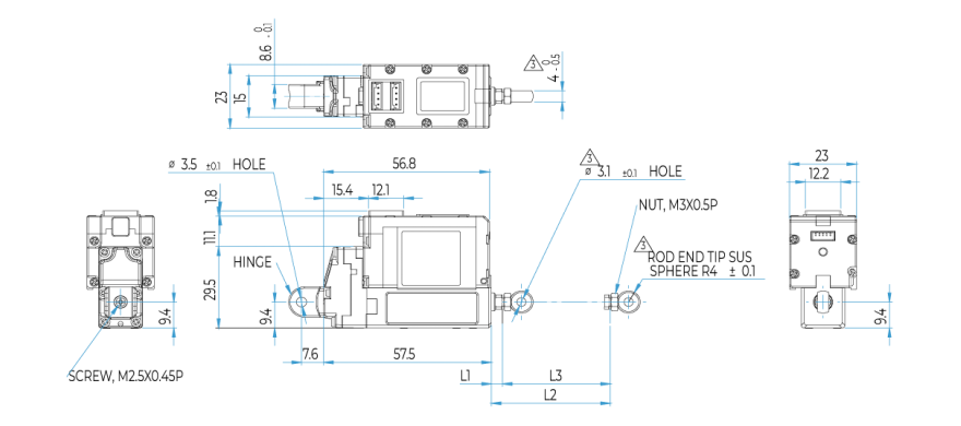
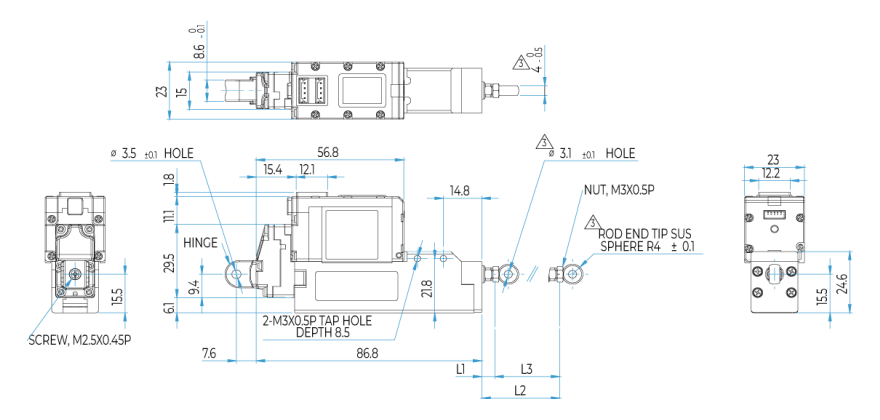
Dimension
UNIT : mm
27mm Stroke
| INDEX | DIMENSION |
|---|---|
| L1 (MIN POSITION) | 3.8 ± 0.5 |
| L2 (MAX POSITION) | 30.8 ± 0.5 |
| L3 (STROKE) | 27 (= L2 – L1) |
37mm Stroke
| INDEX | DIMENSION |
|---|---|
| L1 (MIN POSITION) | 5 ± 0.5 |
| L2 (MAX POSITION) | 42 ± 0.5 |
| L3 (STROKE) | 37 (= L2 – L1) |
50mm Stroke

| INDEX | DIMENSION |
|---|---|
| L1 (MIN POSITION) | 6 ± 0.5 |
| L2 (MAX POSITION) | 56 ± 0.5 |
| L3 (STROKE) | 50 (= L2 – L1) |
87mm Stroke

| INDEX | DIMENSION |
|---|---|
| L1 (MIN POSITION) | 8 ± 0.5 |
| L2 (MAX POSITION) | 95 ± 0.5 |
| L3 (STROKE) | 87 (= L2 – L1) |
17Lf Servo Series Standard Accessories
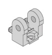
Hinge Base 1pc

Hinge 1pc

Hinge Shaft 1pc

SUS Rod End Tip 1pc

M3 NUT 3pcs

M2.5×6 Screws 3pcs

Socket Set Screw 1pc

Socket head M3.0x8 mounting bolt 3pcs (40mm – 95mm Stroke line-up only)

Wire 4Pin Molex to Molex (RS-485), 200mm
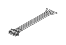
Wire 5Pin Molex extention I/O Cable, 200mm
Wrench for M3 NUT 1pc
Example for Application of Standard Accessories
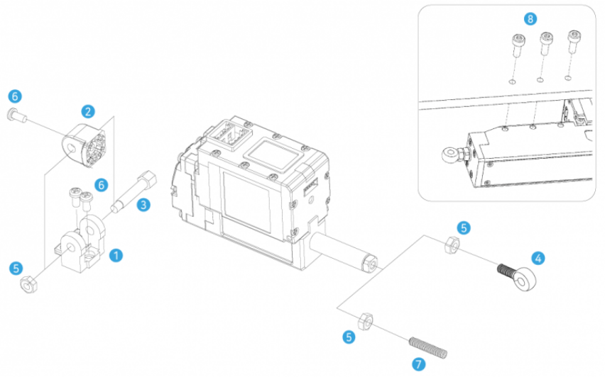
 2Hinge is rotatable by 90degree according to the mounting condition. Without hinge, actuator can be mounted using IR-MB06 (for 27mm stroke version) or IR-MB07 (for 37/50/87mm stroke version) Metal brackets. Also, IR-EB01 Rid end bearing is also one of mounting option. Please refer to the mounting manual for each accessory.
 8SUS Rod-end tip and
  7 soket-set screw can be used according to user’s need.
Or, user may apply their own rod-end tip(M3 standard). Make sure to put  5 M3 nut before applying rod-end tip. The M3 nut is a double nut concept for angle adjustment of rod-end tip mounting.
When mounting rod-end tip, make sure to fix the M3 nut and the rod-end tip by the tool (such as long nose) to set angle and to prevent the rod from turnig together. (If not, it may cause damage to the product. the rod should not be turned all the time.)