Product
mightyZAP, the micro linear servo actuating solution
for the era of the 4th industrial revolution
Actuator Lineup Details
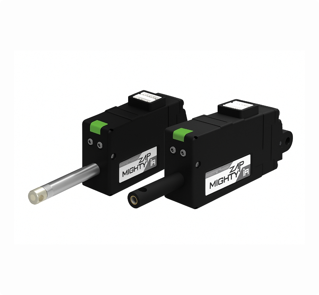
12L / 12D MINI / NANO Limit Switch Series Overview
Mini/Nano Size
Built-in Limit Switches
Max 22mm Stroke (12L / 12D MINI)
Max 15mm Stroke(12D NANO)
Heavy Duty, Durable 12V Coreless Moter Lineup (12L MINI)
Economical 12V / 7.4V Cored Motor Lineup (12D MINI & NANO)
12L / 12D MINI Limit Switch Series Features
- Built-in limit switches, DC motor and gear box without drive circuit & potentiometer.
- Simple & easy linear operation (No servo data communication)
- Reasonable cost comparing to 12Lf and L12 servo actuators
- 12mm diameter 12V coreless motor lineup and cored motor lineup and 12V / 7.4V Cored motor lineup
* The coreless motor is superior to the cored motor in terms of force and durability. - 22mm stroke (Longer stroke options to be released later)
- Rated Load of 12N ~ 100N according to gear ratio for each stroke
- Stroke limit adjustable using external limit switch.
12L / 12D MINI Limit Switch Series Digital Archive
12D NANO Limit Switch Series Features

- The smallest nano-sized actuator in our product lineup
- Operates by limit switches enabling reciprocating motion between two fixed points
- Highly compact, fully integrated design including control circuit, limit switches, DC motor, gearbox, lead screw, and rod
- More cost-effective than mightyZAP servo actuator models such as 12Lf, 17Lf, and 12Df
- Simple plug-and-play installation with immediate operation — no communication control required
- Equipped with a 12 mm diameter, 12 V cored DC motor
- 15 mm stroke
- Rated load options of 7 N or 12 N, depending on gear ratio
- Stroke length can be freely adjusted within 15 mm by adding external limit switches

12D NANO Limit Switch Series Digital Archive
12L MINI Limit Switch Series Specifications
| Rated Load | Stroke | Input Volt : 12V | Rated Load / Max Speed (No Load) | Mechanical Self Lock (Z Axis Use) | Gear Ratio / Gear Type | Motor Type / Watt |
|---|---|---|---|---|---|---|
| 35N | 22mm | 12L-35S-22 | 35N / 28mm/s | Yes (Applicable) | 10:1 / Engineering Plastic gears | Coreless DC Motor / 3.5W |
| 55N | 12L-55S-22 | 55N / 15mm/s | 20:1 / 4 Metal & 2 Engineering Plasticgears | Coreless DC Motor / 3.5W | ||
| 100N | 12L-100S-22 | 100N / 7.7mm/s | 50:1 / 4 Metal & 2 Engineering Plasticgears | Coreless DC Motor / 3.5W |
12L MINI Limit Switch Series Common Specifications
| Stroke | 22mm | |||||
|---|---|---|---|---|---|---|
| Repeatability (Unidirectional) | 500μm (0.5mm) | |||||
| Mechanical Backlash | 0.03mm (30μm) | |||||
| Rod Type | Metal Alloy Rod | |||||
| Motor Type | Coreless DC Motor | |||||
| Watt | 3.5W | |||||
| Recommended Duty Cycle | At Rated Load | At Max Applicable Load | ||||
| Max 50% | Max 20% | |||||
| Input Voltage Range | 7 ~ 13V (Rated 12V) | |||||
| Current Consumption | Idle | Rated | Max (Stall) | |||
| 50mA | 380mA | 1.5A | ||||
| Audible Noise | Approx. 50db at 1m | |||||
| Ingress Protection | IP-54 (Dust & Water Tight) | |||||
| Size / Weight (Excluding rod-end & hinge) | 57.4(L)x29.9(W)x15(H)mm / 48g | |||||
| Operating Temperature | -10℃ ~ 60℃ | |||||
| Wire Harness | 0.08×60 (AWG 22), 300mm | |||||
(*): Maximum stroke length when adjusting long stroke limit through Total Manager software
Dimension
Coreless Motor / 22mm Stroke

| INDEX | DIMENSION |
|---|---|
| L1 (MIN POSITION) | 3.8 ± 0.5 |
| L2 (MAX POSITION) | 25.6 ± 0.5 |
| L3 (STROKE) | 21.8 (= L2 – L1) |
Cored Motor / 22mm Stroke

| INDEX | DIMENSION |
|---|---|
| L1 (MIN POSITION) | 6.5 ± 0.5 |
| L2 (MAX POSITION) | 28.3 ± 0.5 |
| L3 (STROKE) | 21.8 (= L2 – L1) |
12L MINI Limit Switch Series Standard Accessories

Hinge Base 1pc

Hinge 1pc

Hinge Shaft 1pc

SUS Rod End Tip 1pc

M3 NUT 3pcs

M2.5×6 Screws 3pcs

Socket Set Screw (M3.0x15) 1pc
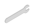
Wrench for M3 NUT 1pc
Example for Application of Standard Accessories
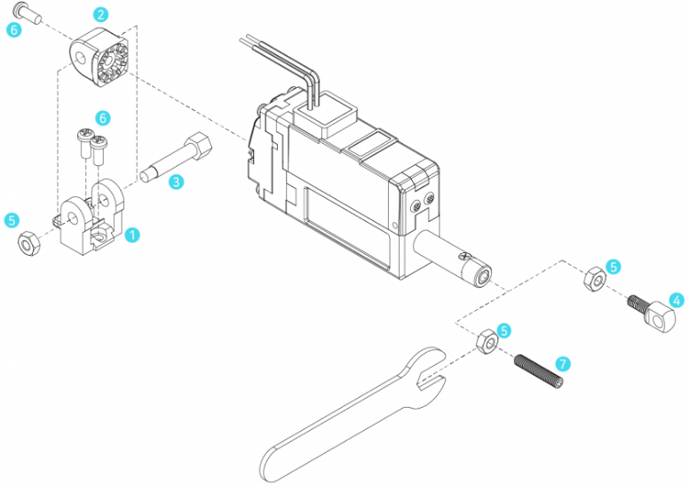
 2Hinge is rotatable by 90degree according to the mounting condition. Without hinge, actuator can be mounted using IR-MB06 (for 27mm stroke version) or IR-MB07 (for 37/50/87mm stroke version) Metal brackets. Also, IR-EB01 Rid end bearing is also one of mounting option. Please refer to the mounting manual for each accessory.
 8SUS Rod-end tip and
  7 soket-set screw can be used according to user’s need.
Or, user may apply their own rod-end tip(M3 standard). Make sure to put  5 M3 nut before applying rod-end tip. The M3 nut is a double nut concept for angle adjustment of rod-end tip mounting.
When mounting rod-end tip, make sure to fix the M3 nut and the rod-end tip by the tool (such as long nose) to set angle and to prevent the rod from turnig together. (If not, it may cause damage to the product. the rod should not be turned all the time.)
12D MINI Limit Switch Series Specifications
| Rated Load | Stroke | Input Volt. : 7.4 or 12V | Rated Load / Max Speed (No Load) | Mechanical Self Lock (Z Axis Use) | Gear Ratio / Gear Type | Motor Type / Watt |
|---|---|---|---|---|---|---|
| 12N | 22mm | 12D7-12S-22 (7.4V) | 12N / 10mm/s | Yes (Applicable) | 10:1 /Engineering Plastic Gears | Cored DC Motor / 0.6W |
| 12D-12S-22 (12V) | 12N / 10mm/s |
12L MINI Limit Switch Series Common Specifications
| Stroke | 22mm | |||
|---|---|---|---|---|
| Repeatability (Unidirectional) | 500μm (0.5mm) | |||
| Mechanical Backlash | 0.03mm (30μm) | |||
| Rod Type | EngineeringPlastic Rod | |||
| Motor Type | CoredMotor | |||
| Motor Watt | 0.6W | |||
| Recommended Duty Cycle | At Rated Load | At Max Applicable Load | ||
| Max 50% | Max 20% | |||
| Input Voltage Range | 7.4V | 12V | ||
| 5 ~ 8.9V | 7 ~ 13V | |||
| Current Consumption | Input Voltage | Idle | Rated | Max (Stall) |
| 7.4V | 50mA | 250mA | 360mA | |
| 12V | 50mA | 140mA | 250mA | |
| Audible Noise | Approx. 50db at 1m | |||
| Ingress Protection | IP-54 (Dust & Water Tight) | |||
| Size / Weight (Excluding rod-end & hinge) | 57.4(L)x29.9(W)x15(H)mm / 48g | |||
| Operating Temperature | -10℃ ~ 60℃ | |||
| Wire Harness | AWG22 | |||
Dimension
Coreless Motor / 22mm Stroke

| INDEX | DIMENSION |
|---|---|
| L1 (MIN POSITION) | 3.8 ± 0.5 |
| L2 (MAX POSITION) | 25.6 ± 0.5 |
| L3 (STROKE) | 21.8 (= L2 – L1) |
Cored Motor / 22mm Stroke

| INDEX | DIMENSION |
|---|---|
| L1 (MIN POSITION) | 6.5 ± 0.5 |
| L2 (MAX POSITION) | 28.3 ± 0.5 |
| L3 (STROKE) | 21.8 (= L2 – L1) |
12D MINI Limit Switch Series Standard Accessories
Hinge Base 1pc
Hinge 1pc
Hinge Shaft 1pc
SUS Rod End Tip 1pc
M3 NUT 3pcs
M2.5×6 Screws 3pcs
Socket Set Screw (M3.0x15) 1pc
Example for Application of Standard Accessories
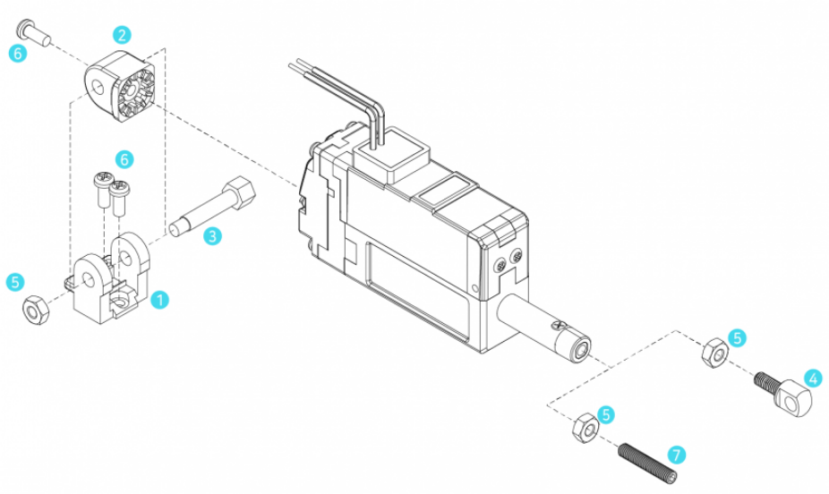
2Hinge is rotatable by 90degree according to the mounting condition. Without hinge, actuator can be mounted using IR-MB06 (for 27mm stroke version) or IR-MB07 (for 37/50/87mm stroke version) Metal brackets. Also, IR-EB01 Rid end bearing is also one of mounting option. Please refer to the mounting manual for each accessory.
8SUS Rod-end tip and 7 soket-set screw can be used according to user’s need.
Or, user may apply their own rod-end tip(M3 standard). Make sure to put 5 M3 nut before applying rod-end tip. The M3 nut is a double nut concept for angle adjustment of rod-end tip mounting.
When mounting rod-end tip, make sure to fix the M3 nut and the rod-end tip by the tool (such as long nose) to set angle and to prevent the rod from turnig together. (If not, it may cause damage to the product. the rod should not be turned all the time.)
12D NANO Limit Switch Specifications
| Rated Load | Stroke | Input Volt. : 12V | Rated Load / Max Speed (No Load) | Mechanical Self Lock (Z Axis Use) | Gear Ratio / Gear Type | Motor Type / Watt |
|---|---|---|---|---|---|---|
| 7N | 15mm | 12D-7S-15 | 7N / 30mm/s | No (Pay attention to application) | 30:1 / 3 line/ Engineering Plastic gears | Brushed Cored DC Motor / 0.26W |
| 12N | 12D-12S-15 | 12N / 11.25mm/s | Yes (Applicable) | 30:1 / 1 line / Engineering Plastic gears |
12D NANO Limit Switch Series Common Specifications
| Stroke | 15mm (± 1mm) | |||
|---|---|---|---|---|
| Repeatability (Unidirectional) | ± 500μm(± 0.5mm) | |||
| Mechanical Backlash | 400μm (0.4mm) | |||
| Rod Type | Engineering Plastic Rod | |||
| Motor Type | Brushed Cored DC Motor | |||
| Motor Watt | 0.26W | |||
| Recommended Duty Cycle | 20% | |||
| Input Voltage Range | 7 ~ 13V (Rated 12V) | |||
| Current Consumption | Input Voltage | Idle | Rated | Max (Stall) |
| 0mA | 20mA | 40mA | 200mA | |
| Audible Noise | Approx. 50db at 1m | |||
| Ingress Protection | IP-54 (Dust & Water Tight) | |||
| Size / Weight | 32(L)x21.5(W)x12(H)mm/ 17g | |||
| Operating Temperature | -10℃ ~ 60℃ | |||
| Wire Harness | Flexible PCB 5P | |||
| Standard Accessories | 2 x U-Type Bracket / 2 x D3x8.6 Hinge / 4 x ID1.5xOD4xT0.4 Snap Ring-E / 2 x M3x8 Screw / 1 x FPCB Connector | |||
(*): Maximum stroke length when adjusting long stroke limit through Total Manager software
Dimension
Coreless Motor / 22mm Stroke
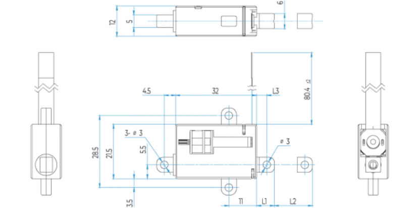
| INDEX | DIMENSION |
|---|---|
| L1 (MIN POSITION) | 7 ± 0.8 |
| L2 (STROKE) | 15 ± 1 |
| L3 | 4 ± 0.8 |
12D NANO Limit Switch Series Standard Accessories

U-Type Bracket 2pcs

Hinge-Pin D3 x 8.6 2pc

E-Ring ID 1.5 x OD4 xT0.4 4pcs

M3 x 8 Screw 2pcs

F-PCB Connector 1pc
Example for Application of Standard Accessories

[Rod-End Side]
1Insert 4M3x8 screw into the middle hole of U-type Bracket and fix the screw to the user’s device. Align the center of the two side holes of U-type Bracket and the side hole of Rod, then insert 2Hinge-pin. After the Hinge-pin protrudes from both ends of U-Bracket, fix the pin by two 3E-rings.
[Rear Case Side]
1Insert 4M3x8 screw into the middle hole of U-type Bracket and fix the screw to the user’s device. Align the center of the two side holes of U-type Bracket and the side hole of Hinge on the rear case, then insert 2Hinge-pin. After the Hinge-pin protrudes from both ends of U-Bracket, fix the pin by two 3E-rings.
* Cuation : Either Rod or Rear case hinge must be mechanically unconstrained and must be structured to move freely along with the actuator.
[F-PCB]
Insert the Terminal of F-PCB so that it can make contact with the 5connector pin. (See the picture below)
if inserted in the opposite direction, the actuator will not work.
